I will try to explain what I could understand of the checkm8 exploit and reproduce it.
This subject is now kind of outdated as maybe everyone already know how it does work but well I do not, so I thought it would be interesting to give a try!
I am not lying, it just… looked scary, all of this was and is still too much for a beginner in vulnerabilties like me… but today I moving out of my comfort zone and I will try to understand it! (๑•̀ㅂ•́)و✧
At first I didn’t want to publish it since I noticed after finishing the writing this article that some write-up were already existing and were somehow much better than mine (I even thought at first that I copied some, which was not the case ;-;) but after all I’ve done, I had to publish it.
Some things may be wrong as I tried to understand by myself without asking that much help so please correct me if I ever say something wrong, this write-up was really written in order to educate myself so… here it is :’)
I hope that you will learn something new or at least will enjoy what I have been doing for the last few months!
Also, I will assume that you have a bit of knowledges in reverse-engineering, embedded programming, etc.
0x1. Basics
In 2019, @axi0mX published out of nowhere a SecureROM exploit which the vulnerabilty can be used from the iPhone 4S (A5) to the iPhone X (A11) devices.
This kind of exploit is very important as Apple can only fix it by releasing new devices as it is related to the SecureROM (Read Only Memory), which allows us to have the highest privileges possible (EL3).
As said, this exploit is targetting the SecureROM, which is the very first component of the bootchain to start (you can read a bit about the bootchain here).
Here is a quick view of the bootchain process:
The checkm8 exploit occurs then at the very beginning of this sequence: when the DFU mode is triggered, and what I am going to do today is to try to reproduce the exploit on my own!
Also, this is thanks to this exploit that amazing projects could have seen the light such as:
- checkra1n jailbreak,
- project sandcastle (which allows us to boot
Linux/Android!), - Bonobo cables (allowing
CPUdebugging throughJTAG/SWD), - checkm8_bootkit (allowing to boot arbitrary
iBootimages), - […]
And also since then, multiple fork of ipwndfu have seen the light for many other devices or using alternative ways such as:
- checkwatch (targetting the Apple Watches)
- checkm8-haywire (targetting Apple’s haywire)
- ra1npoc (allowing to use
checkm8using an already jailbroken device) - […]
Anyways, enough talking: let’s see how it works! (^∀^)
0x2. Apollo
Some few times after the release of checkm8, @littlelailo published a gist about an Apple BootROM bug which appeared to be the same bug as checkm8.
The interesting thing there is that there is only a few exploitation explaination without that much details and no big lines of code (nor tool) provided, making that gist a great training for today: I will try to understand the bug only by following this kind of guide.
Let’s get into it :)
0x21. Step 1 (Starting)
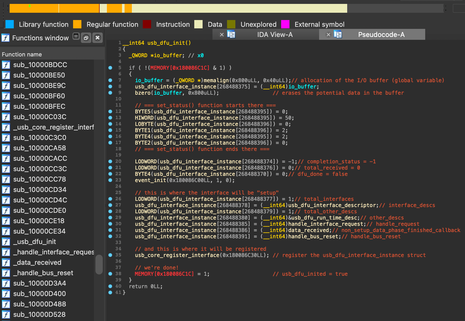
1: “When usb is started to get an image over dfu, dfu registers an interface to handle all the commands and allocates a buffer for input and output”
DFU is a mode where you should be allowed to restore your device from any state (and is also a part of the SecureROM).
From what I understood, when you enter in DFU mode, a certain function called usb_init_with_controller(...) is called to init the USB Stack so it can communicate with a host in order to receive an image and exit this “emergency” state.
In this context, the function usb_core_init(…) is being invoked, which is the one indirectly referenced in the previous statement.
Globally, this function has for purpose to register a new
DFUinterface that will perform all of the required state management and communications with the connected host in the hope to receive a new firmware.
The buffer mentioned here is a global variable from the Interface Code called io_buffer, which is allocated by the memalign(3) function. Its purpose is to temporarily store the received data.
Then, the function will continue its process by registering an interface (which is the communication way between the device and the computer) that will handle all USB transfers/transactions/[…] thanks to a structure called usb_interface_instance (which is also a global structure):
The pseudo-code you are currently viewing was taken from an
A7 SecureROM, you can pick it up here (but I mostly used theiBootsource code)
Once this function has been successfully executed, the process continues until completion, and the device is officially placed in the DFU state, allowing us to proceed to the next step.
Please keep in mind the
usb_interface_instancestructure fields, it will be useful and explained later.
0x22. Step 2 (USB)
2: “if you send data to dfu the setup packet is handled by the main code which then calls out to the interface code”
For this step, please take a deep sit because this is going to be a long one.
Because this part will actually treat about the USB basics and some other things related to the Interface / Main code.
0x221. Basics
Actually, I had like no knowledge at all about all of this USB stuff and all, that’s why I will try to detail what I understood (please correct me if I’m wrong).
One thing you need to know is that the DFU mode accepts something called “control transfers”: these “transfers” are typically initiated by the host to perform various operations on the device and are working in “phases” (you can read more if you really want a more complete explaination here):
The
hostis the device that initiates and controls the communication, in short: that’s us
Technically, every USB devices must have a sort of “default configuration” in order to answer when a
SETUPpacket is sent.
Also, a packet usually (no matter which phase it actually is) looks like this:
These are the main fields, a plenty of other libraries can deal with the control transfers (and has differents prototypes) but you got the idea
bmRequestType: indicates the direction of the request (if it’s a request from the device to the host or the opposite),bRequest: this actually indicates what kind of control request we’ve sent but will mostly depends on the bmRequestType field (I will talk about it later),wValue: specifies the information that needs to be passed from host to device, such as the ability to set/get the USB descriptor or configuring device features (for example),wIndex: similar aswValueexcept that this is with this field you can pass the endpoint or interface number (as we are working with descriptors),Data: it’s a buffer that contains the data of the control request (input or output depends on the specific request and its direction),wLength: should match the size of theDatafield and indicates how much data is being transferred from the host to the device or the opposite.
0x222. Endpoints
If you read what I’ve wrote carefully, you may have noticed something called the “endpoint”:
- From what I understood, the
endpointis a specific address within a USB device where data is sent/received. It can hold a buffer but also defines the type of data and transfer specificities (control,bulk,interruptorisochronous) that can be transferred using it.
Every devices should have an “endpoint at the address 0x0” (also known as
EP0).
The
EP0purpose is that you can send AND receive data within a single transfer, but also (and more importantly) to be reserved for every control transfers which gives to the host the ability to read the device descriptor tables (corresponding to the setup part previously done in order to enter inDFUmode) and to send control commands to the device during normal application execution.For example, EP0 is used to indicate the end of a packet transfer, which is important for the proper functioning of USB communication protocol processes.
Phew, that was something… and we’re absolutely not done yet ٭(•﹏•)٭
0x223. Standard Interface Requests
As you saw previously, there’s a field called bmRequestType and another called bRequest and these are vitals in a control transfer.
I was looking at the iBoot source code and I found a comment that I found interesting about that:
And so, here we go: welcome to Yui’s class, please take a sit:
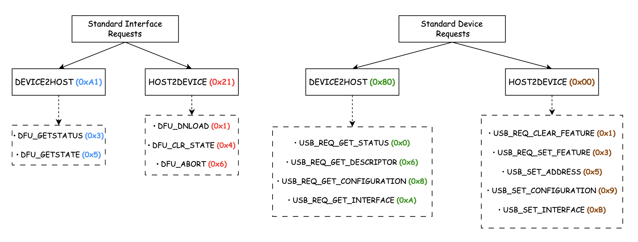
The content that you’re about to see is called the Standard Interface Requests, they are name-specific to the DFU interface but are basically used to configure and control the behavior of the current interface within the USB device (here the DFU).
Actually, there are two types of bmRequestType (and plenty of bRequest for each of them):
DEVICE2HOST(its value is0xA1) and its availablebRequestare:DFU_GETSTATUS(0x3): allow the host (that’s us) to get the device’s status,DFU_GETSTATE(0x5): same as the status except that instead of the status, we’re getting the device’s current state.
HOST2DEVICE(its value is0x21) and its availablebRequestare:DFU_DNLOAD(0x1): allow data transfers from the host (that’s still us) to the device,DFU_CLR_STATUS(0x4): clear the status and exits theDFUmode,DFU_ABORT(0x6): same asDFU_CLR_STATUS.
The
DFU_CLR_STATUSandDFU_ABORTrequests are the same, even though the names are different.
0x224. Standard Device Requests
In addition to the requests mentioned earlier, there’s also something called Standard Device Requests which are essentials for device enumeration/configuration/… and any other control transfers that apply to the entire device: they are essentials for the device overall functionality and provide a standard way for the host and device to communicate/configure the device.
So, there are, again, two types of bmRequestType (and still plenty of bRequest):
DEVICE2HOST(its value is0x80) and its availablebRequestare:USB_REQ_GET_STATUS(0x0): allows us to get the status of the device,USB_REQ_GET_DESCRIPTOR(0x6): allows us to request a descriptor that can provide information (such as the device configuration, interfaces, endpoints, …),USB_REQ_GET_CONFIGURATION(0x8): allows us to get the current device configuration (how the device operates, which interfaces are active, …),USB_REQ_GET_INTERFACE(0xA): allows us to get the current interface setting (such as: which alternate setting is active, …).
HOST2DEVICE(its value is0x00) and its availablebRequestare:USB_REQ_CLEAR_FEATURE(0x1): allows us to clear a specific feature of the device,USB_REQ_SET_FEATURE(0x3): allows us to set a specific feature of the device,USB_REQ_SET_ADDRESS(0x5): allows us to set the USB address of the device (after, the communication between the device and the host will be established using this address)USB_REQ_SET_CONFIGURATION(0x9): allows us to set the device configuration,USB_REQ_SET_INTERFACE(0xB): allows us to set the device interface.
Note that the
HOST2DEVICEbRequestare not that much explained since they’re pretty much already explained in theDEVICE2HOSTbRequest.
Well, whether it’s configuring or managing the device, both Standard Interface Requests and Standard Device Requests own different roles which in the end eases the communication/control/… between the device and the host (I thought it was important to mention this since many USB requests use these parameters, though I agree it can be a bit confusing-).
So now, you can also guess that when we are talking about the main code, we are in fact talking about the USB Core and when we are talking about the interface code, we’re talking about the DFU’s USB part, this will really be useful for the next part.
We should be alright now, this was huge and complex but we made it, let’s move foreward! (disclaimer: this is not the end-)
0x225. Packet Handling
In this step, it’s mentioned that the packet is first handled by the main code so we’ll look forward to this.
I will not lie, my first researche were false because I looked at the Interface Code and not the Main Code (which was correct in the end but not entierly, I really was confused by everything, I must confess), but now that we’ve seen how to differenciate them, we can now make things right!
So! in order to find the function that actually handles the packet, you have to dig pretty deep into the code (so I will not detail how far I searched but) the one I found is called usb_core_handle_usb_control_receive(...).
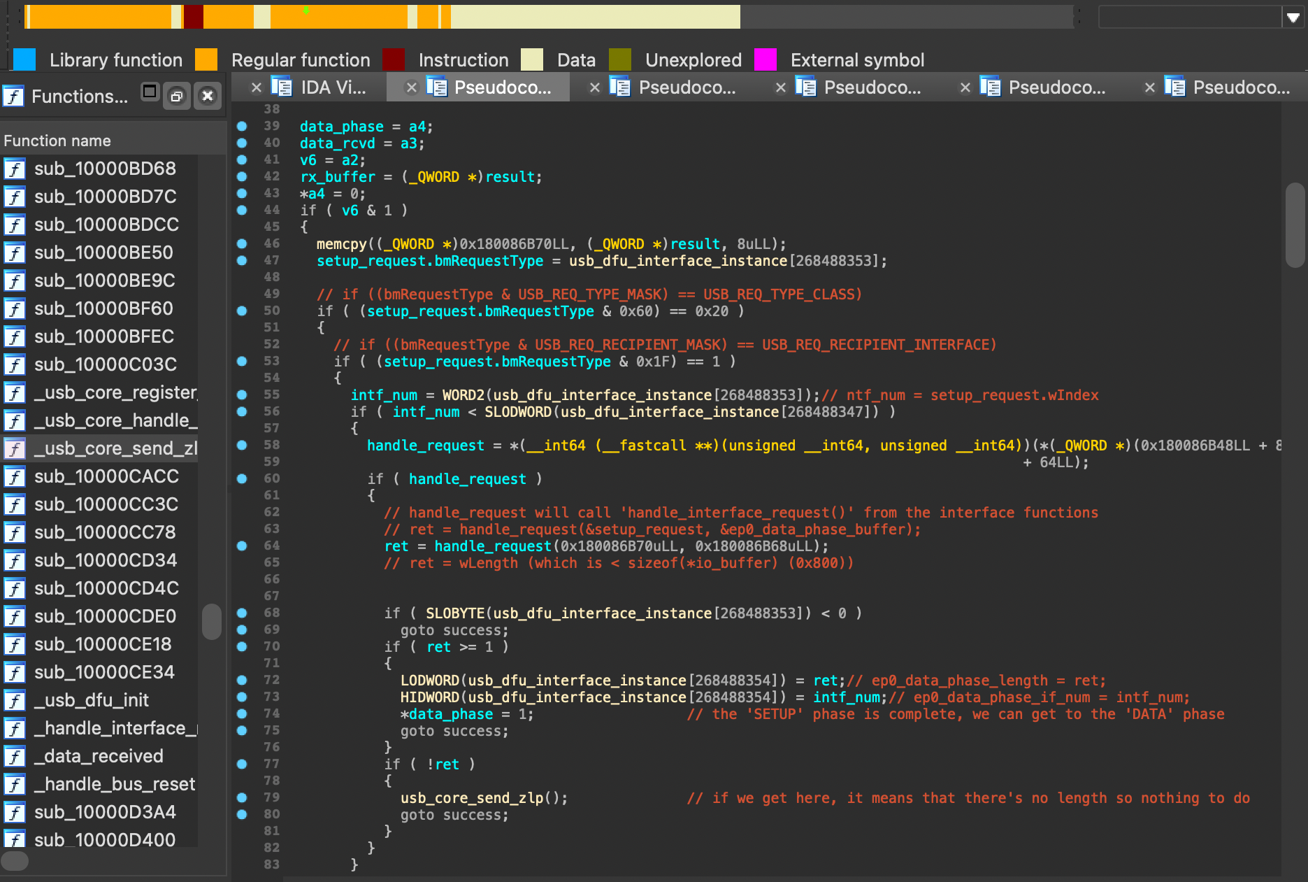
It seems that this function is the one that handles the SETUP packets (and will call another function called handle_ep0_data_phase(...) if the packet received is a DATA one), so the following pseudo-code is the one that will be executed when a SETUP packet is received:
The
usb_dfu_interface_instancestructure is the one we’ve talked about earlier (it contains the elements when theDFUinterface was registered, […]).
From what I understand, if the bmRequestType is correctly set and if the bRequest is a USB_REQ_HOST2DEVICE one, then the function will call a member of usb_dfu_interface_instance: this member is a function pointer pointing to the handle_interface_request(...), which is an interface function (this is where we will jump from the main code to the interface code).
This point is leading us to the next part.
Also, if you’ve read carefully then you saw that once the
usb_core_handle_usb_control_receive(...)function is done, it will jump to alabelcalledsuccesswhich will only tell that theDATA Phasecan be started, not that much interesting to show.
0x23. Step 3, 4, 5 (Update)
3, 4, 5: “the interface code verifies that wLength is shorter than the input output buffer length and if that’s the case it updates a pointer passed as an argument with a pointer to the input output buffer”
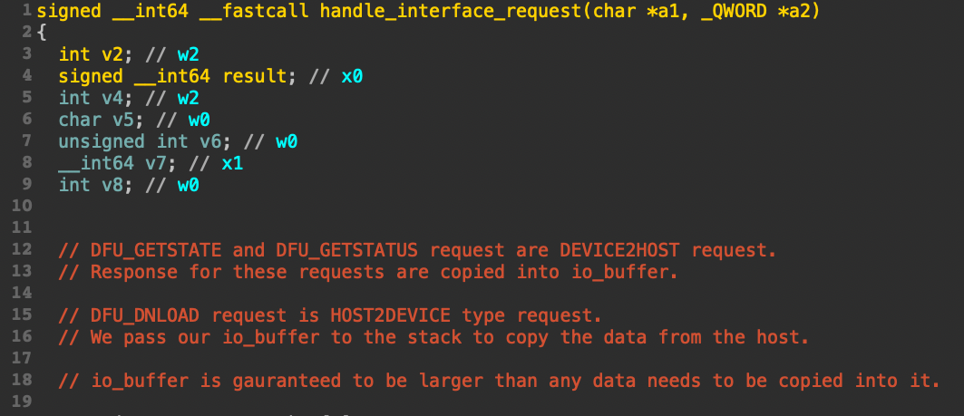
When the main code jumps to this interface function, the first thing I’ve noticed was that this function handled the two interface bmRequestType available and all of their bRequest.
However, in our case we are only interested in the HOST2DEVICE request, in particulary the DFU_DNLOAD bRequest (which is the one that allows us to send data to the device, if you followed until there then I don’t think I need to explain why).
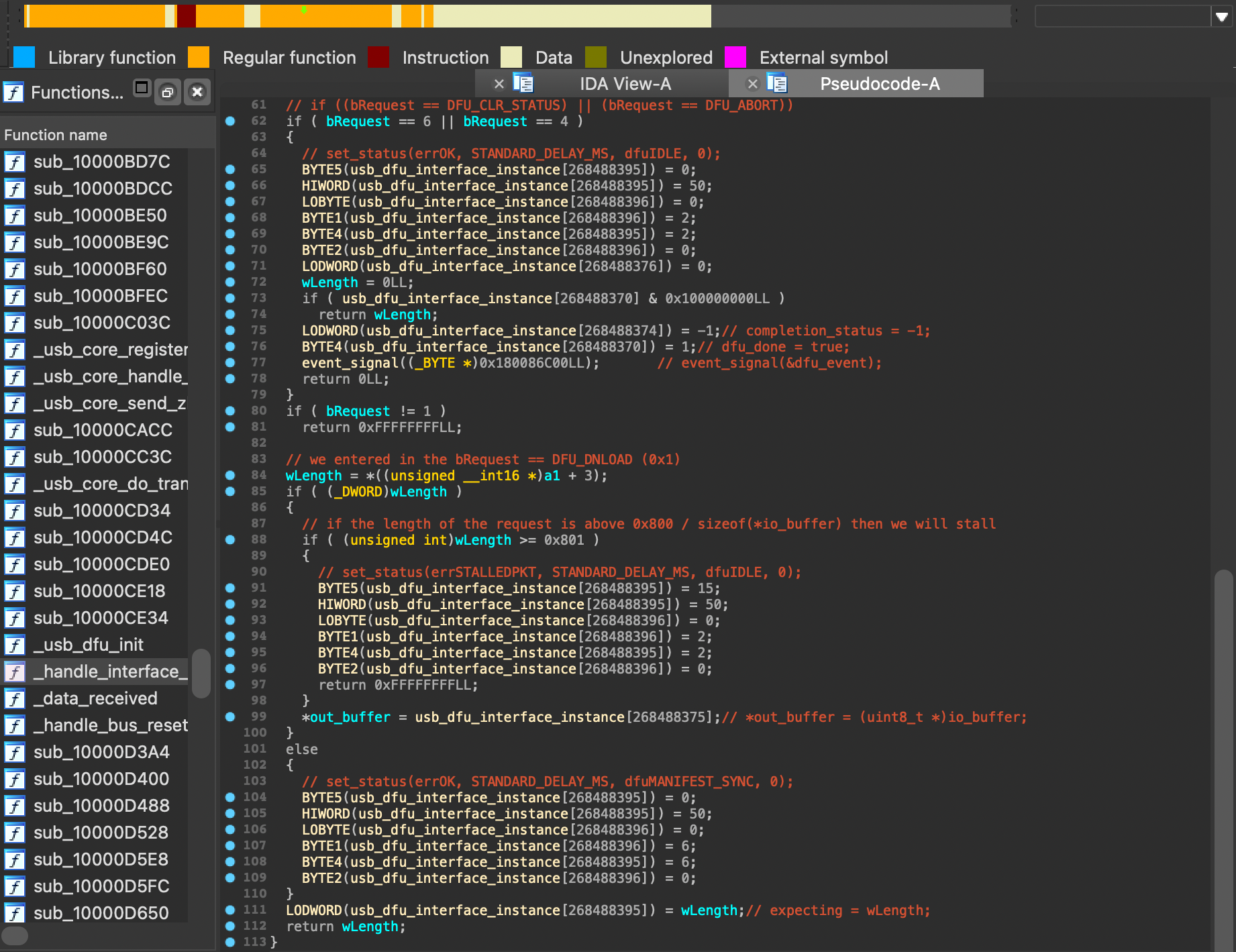
As the statement says, when the function enter in the condition where the bRequest is equal to DFU_DNLOAD, it will check if wLength is shorter than the io_buffer total allocated length (which is 0x800).
However, the pseudo-code is showing the case where
wLengthis bigger than theio_bufferlength which will makeDFUstalling (the logic is still the same though).
That aside, the main point of this function is to update the ep0_data_phase_buffer pointer to take the address of the io_buffer, which is the buffer of the interface code that will be used for the DATA Phase and that contains allocated memory for the data received (see usb_dfu_init(...)).
The function will then returns wLength and will jump back to the main code (a.k.a usb_core_handle_usb_control_receive(...)).
We can now move on to the next part!
0x24. Step 6 (Buffer Filling)
6: “if a data package is recieved it gets written to the input output buffer via the pointer which was passed as an argument and another global variable is used to keep track of how many bytes were received already”
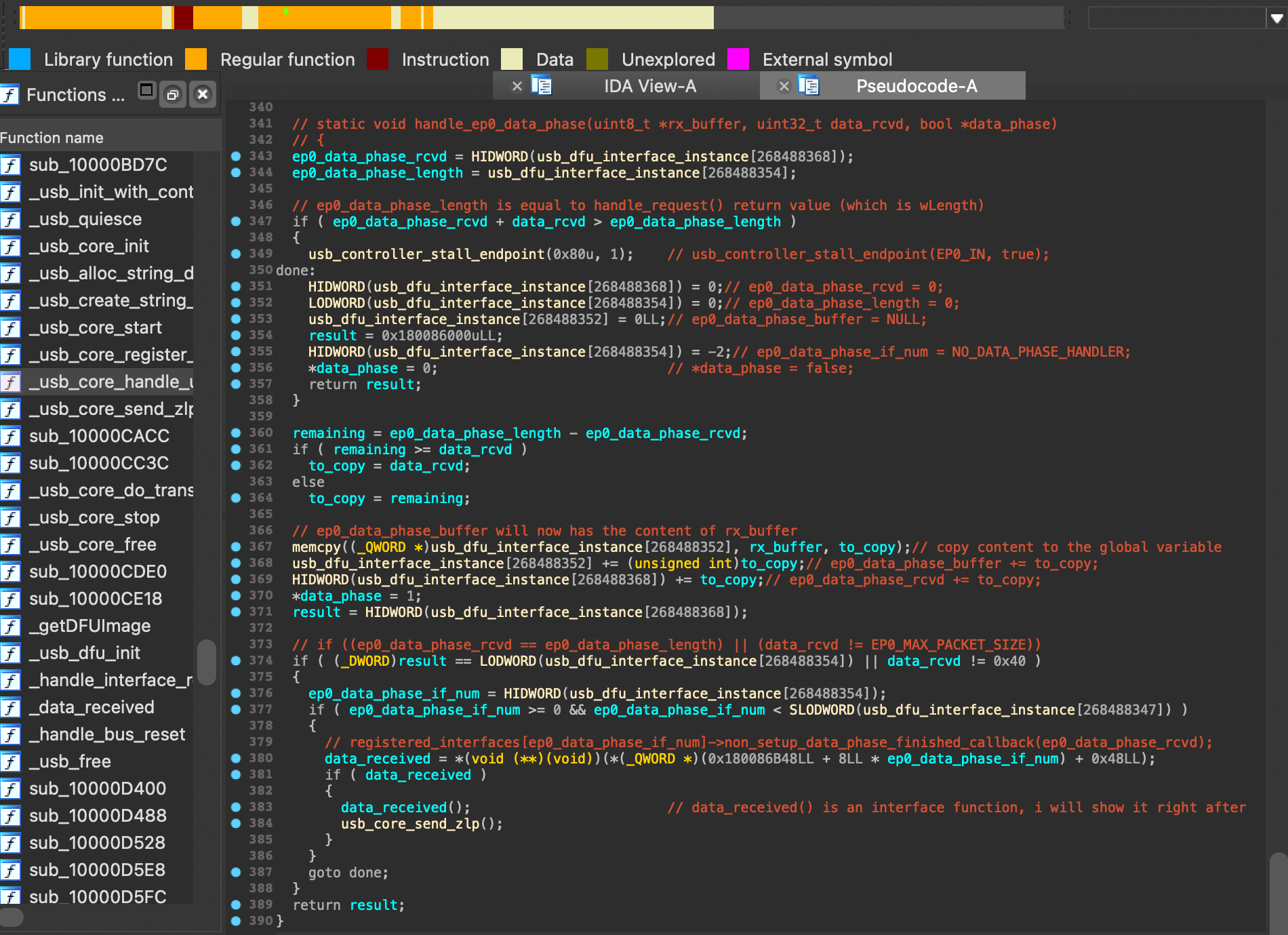
Then, here comes the DATA Phase, which is handled by the function handle_ep0_data_phase(...) (which is called by the function usb_core_handle_usb_control_receive(...)… again… phew~).
This function was a mess to disassemble, it was complicated to figuring out what’s going on, just see by yourself…
Globally, this pseudo-code is already speaking from itself, but as it is pretty messy all those comments, I will try to explain it in a more understandable way:
First, it will checks if adding the received data (ep0_data_phase_rcvd) to the previously received data (ep0_data_phase_rcvd) exceeds the expected data phase length (ep0_data_phase_length).
If it does, the code stalls the EP0_IN endpoint (this endpoint is used for sending data from the USB Device to the host) and then clear the global variables.
Second, it will uses the memcpy(...) function to copy the content from rx_buffer to the ep0_data_phase_buffer (which will be then updated to point to the next available position in the buffer, etc.). and state that the DATA Phase is still in progress.
Just a quick reminder to tell that
rx_bufferhas theio_bufferaddress
Finally, if either the entire expected data has been received or the received data doesn’t fill up a full packet (if we sent 0x26 out of 0x40 bytes for example), it will complete the data phase by checking up if there is a non-null callback function registered from the interface (which should be a function called data_received(...)).
If there is, then it will call and jump to this function, which is the one we will talk about in the next part.
0x25. Step 7 (Copy Buffer To Insecure Memory)
7: “if all the data was received the dfu specific code is called again and that then goes on to copy the contents of the input output buffer to the memory location from where the image is later booted”
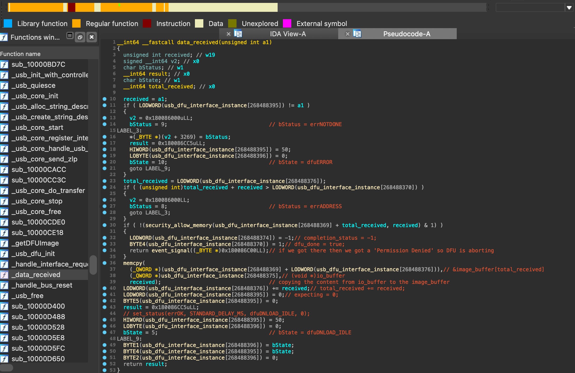
We just talked a non-null callback function called data_received(...) (which is called when the expected data has been received).
I will not detail everything but there is an interesting part in this screenshot: the security_allow_memory(...) function.
1
if (!(security_allow_memory(usb_dfu_interface_instance[...] + total_received, received) & 1))
This function is the one that will copy the content of the io_buffer to the memory location said by the statement (called the INSECURE_MEMORY) from where the firmware (IMG4) is later booted as DFU is supposed waiting for an image (so you can easily guess that it is a very sensitive zone).
If everything went well then it will jump back to the handle_ep0_data_phase(...) function, send a Zero-Length Packet and finally resetting the global variables such as ep0_data_phase_length, ep0_data_phase_buffer etc. (these are global state variables that are used to keep track of the DATA Phase).
Also, sending a
ZLPpacket is mandatory as it “prevent” issues that could arise due to incomplete or unsynchronized data transfers.
0x26. Step 8, 9 (Done)
8, 9: if dfu exits the input output buffer is freed and if parsing of the image fails bootrom reenters dfu
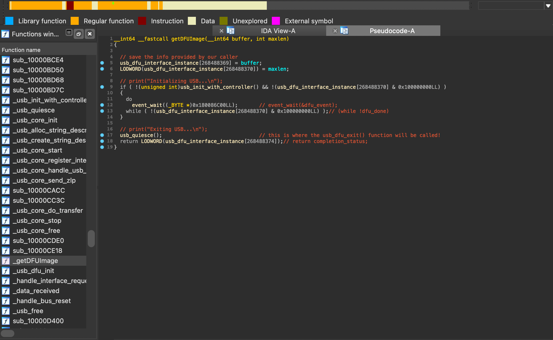
All you’ve see from now was originally executed from this function: getDFUImage(...): this is the one that is responsible for calling the right functions that will handle the DFU image awaiting and the USB initialization/ending of the DFU mode.
Only if the
USBinitialization is successful, theDFUmode will wait for thedfu_donevariable to be set totrue(which is the case in thedata_received()function or by sending aDFU_ABORT/DFU_CLR_STATUSpacket or by sending anUSB Reset), making it stop.
At this point of the explaination, we’ve reached the end of this function (assuming we’ve sent data so the io_buffer isn’t empty).
A function called usb_quiesce() will call several functions that will stop the USB tasks, reset the USB controllers/descriptors, etc. in summary: it will shutdown the USB Stack.
Keep in mind that among these shutdowns, the
EP0_IN/EP0_OUTendpoints will also be aborted and stopped (thanks to a function calledsynopsys_otg_stop(void)).
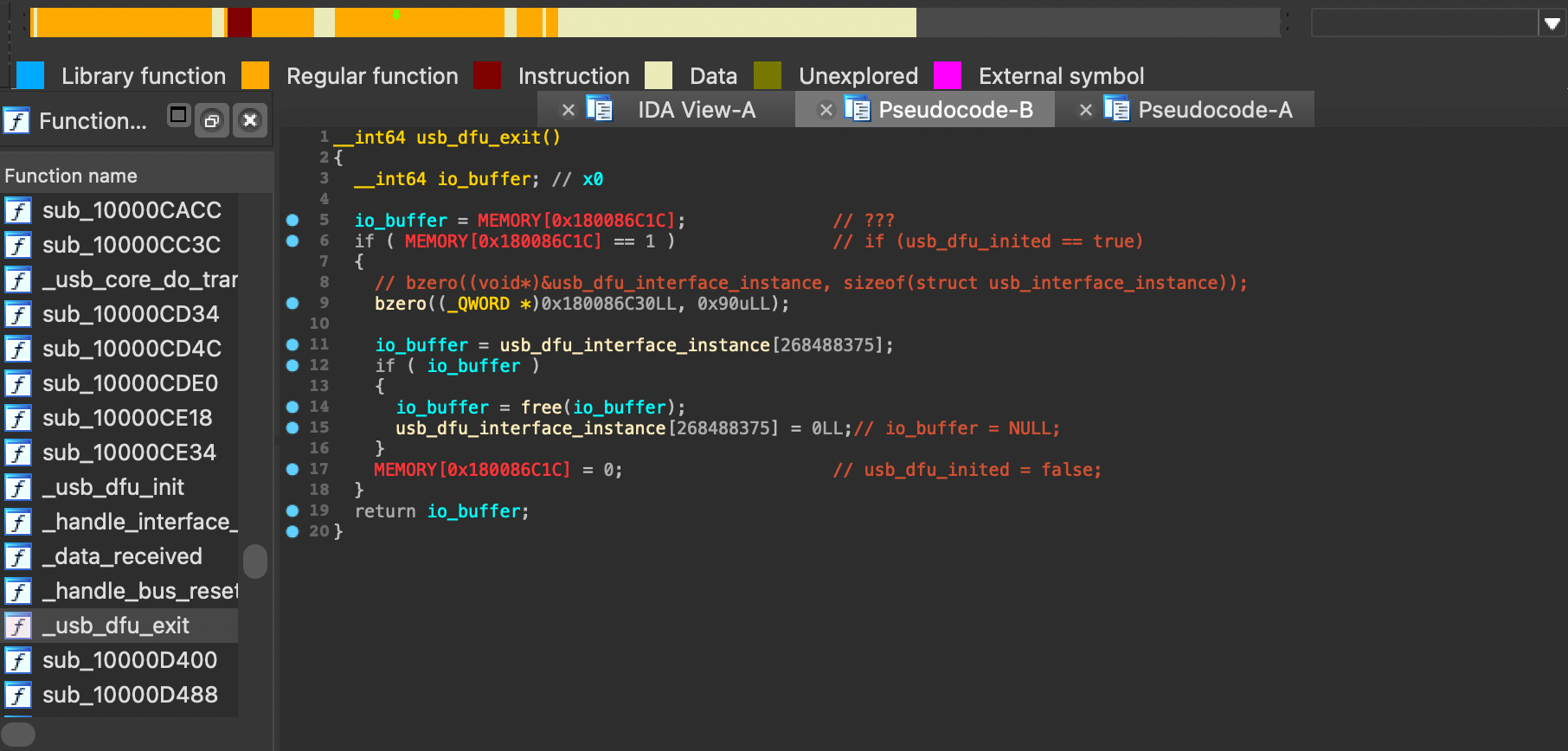
One of these functions is called usb_dfu_exit(void) and this is the one that is responsible for resetting the interface which handled all commands (thanks to the bzero() function) and, if the io_buffer is not empty, freeing then NULLing it (because it don’t have any use any more, we wouldn’t want an Use-After-Free… right? :)).
The pseudo-code is slightly messed up since the beginning but I tried to make it as readable as possible using the iBoot source code
Then, it will jump back to the getDFUImage(...) function and, depending on the return value (called completion_status), the DFU will either be restarted/reentered, either be booted later (which is slightly out of context from this point).
We are now DONE with the explaination part, that was hard but well done for still being there!! (ノ◕ヮ◕)ノ*:・゚
0x27. Summary
I admit, this is TOO MUCH informations to process at once, so I will try to summarize everything we’ve seen so far.
About the global process of the DFU mode, here’s a very abridged draw of what we’ve seen:
I know that this is not an accurate draw, but as the tittle says: it’s just a summary :)
And of course, I made another abridged draw of the differents requests we’ve seen:
Not that my memory is kind of limited but I really don’t always remember everything so I made this draw to help me remember the requests names and values
However, in all of this process, a certain vulnerability is occuring, and this is what we will see in the next part.
0x3. Exploitation
And so, here we are: the exploitation part.
I was wondering “how in the world is it even possible to find a vulnerability in all of this complex algorithm??” and to be really honest: I wouldn’t have been able to find it by myself.
0x31. Use-After-Free
As @littlelailo said:
1
2
3
4
5
6
7
8
9
10
11
12
13
14
15
At step 5 the global variables are updated and the bootrom gets ready to recieve
the data, but with a cheap controller you can violate the usb spec and don't
send any (arduino host controller or sth like that).

Then you can trigger a usb reset to trigger image parsing. If that parsing fails
bootrom will enter dfu once again, BUT step 8 (code resets all variables and
goes on to handel new packages) wasn't executed so the global variables still
contain all the values.

However step 9 (when input output buffer is freed) was executed
so the input output buffer is freed while the pointer which was passed as an
argument in step 3 still points to it.

Because of that you can easily trigger a write to an already freed buffer by
sending data to the device.
What this text is saying is that in this whole logic, an Use-After-Free is occuring.
Why? Because the io_buffer is freed but the pointer that points to it (ep0_data_phase_buffer, do you remember?) is still valid.
Based on the summary draw I’ve made earlier, here’s what’s supposed happening:
This may be a little bit confusing, but this is summaring what @littlelailo said.
In another terms:
- Get into the
DATAphase / to the point where the global variables are updated, - From there, we can send a
DFU_ABORT/DFU_CLR_STATUSnor anusb_resetrequest (which will set thedfuDonevariable totrue, stopping allDFUactivities), - The
usb_quiesce(...)function (we previously saw) will free theio_bufferand shutdown theUSB StackBUT the global variables (from thehandle_ep0_data_phase(...)function) will not be clear as the transfer will not be complete, - Then the
getDFUImage(...)function we previously saw will be re-executed but the global variables will not be reinitialized, making theep0_data_phase_bufferstill pointing to the previousio_bufferaddress, which is now freed.
ep0_data_phase_buffer = NULL: by NULLing the pointer, we are telling that we will not reuse the actualio_bufferpointer anymore and this is the right thing to do in order to prevent “undefined behaviors”…
however, as we skipped the “variables resetting” part, the pointer is still pointing to the previousio_buffermemory location and, as we are dealing with aROM(highly (but not fully) predictable so), there’s high chances that the buffer’s address will be the same for each newDFUiterations, which is what we don’t want since it would not be anUaFanymore.
This is amazing, but apparently not enough to exploit the vulnerability…(;へ:)
0x32. Memory Leak
But then, how could we exploit this vulnerability without the io_buffer having the same address?
Well, we then would need a work-around in order to prevent this to happen, and luckily, there’s apparently a way to do so: a Memory Leak (!!!) that will hopefully allow us to control the heap in order to finally allocate the io_buffer further away from the former one’s address.
A
Memory Leakoccurs when a program allocates memory from the heap but fails to free it back, leading to data remaining allocated but not accessible.
This part will probably be the most complicated one, so please take a deep sit and let’s get into it!
I will not lie, I was kind of stuck there and at this same time, until I saw on Twitter some slides made by @qwertyoruiopz, which was very useful and which I really recommand to take a look at!
So I read it and I found the part that interested me:
1
2
3
4
5
6
7
8
9
10
In-flight USB transfers will have an associated structure allocated on the heap,

We have the ability to repeatedly malloc and delay the free temporarily,
until the IN endpoint of the device-to-host stall conditions are cleared
or the USB stack is shut down,

A state machine bug in the USB stack is abused in order to have allocations
that persist across USB stack destruction and creation.

(Memory Leak!!!)
SO, I will detail each points in order to understand what’s going on.
I had to search for that “associated structure” and I found one called usb_device_io_request and defined as the following:
1
2
3
4
5
6
7
8
9
10
struct usb_device_io_request
{
    u_int32_t                       endpoint;
    volatile u_int8_t               *io_buffer;
    int                             status;
    u_int32_t                       io_length;
    u_int32_t                       return_count;
    void (*callback)                (struct usb_device_io_request *io_request);
    struct usb_device_io_request    *next;
};
This structure can handle asynchronous operations thanks to the
callbackfield (which is a function pointer that will be called once the request is completed), and thenextfield (which is a pointer to the nextio_requeststructure in the linked list of requests, allowing a queue).
It is mentioned that stalling (or halting) the DEVICE2HOST is involved in this process, so I had to search for that.
The fact is that when you stall/halt the IN endpoint, you can actually send requests but they will not be executed right away; instead, they will be queued in the linked list until the IN endpoint is unstalled while allocating space for each request in the heap.
However, when the IN endpoint is unstalled, all of these requests will be freed and de-allocated… so, isn’t this giving us the ability to allocate as much as we want and delay all free(...) of the objects on the heap-? (spoiler: YES!)
We somehow have a great vector of attack but sadly slightly superficial, because all of those allocations will not remain through a shut down of the USB Stack… that’s when the Memory-Leak enters!!
Finally, the “abused state machine bug in the USB stack” is foundable right in the callback of the usb_device_io_request:
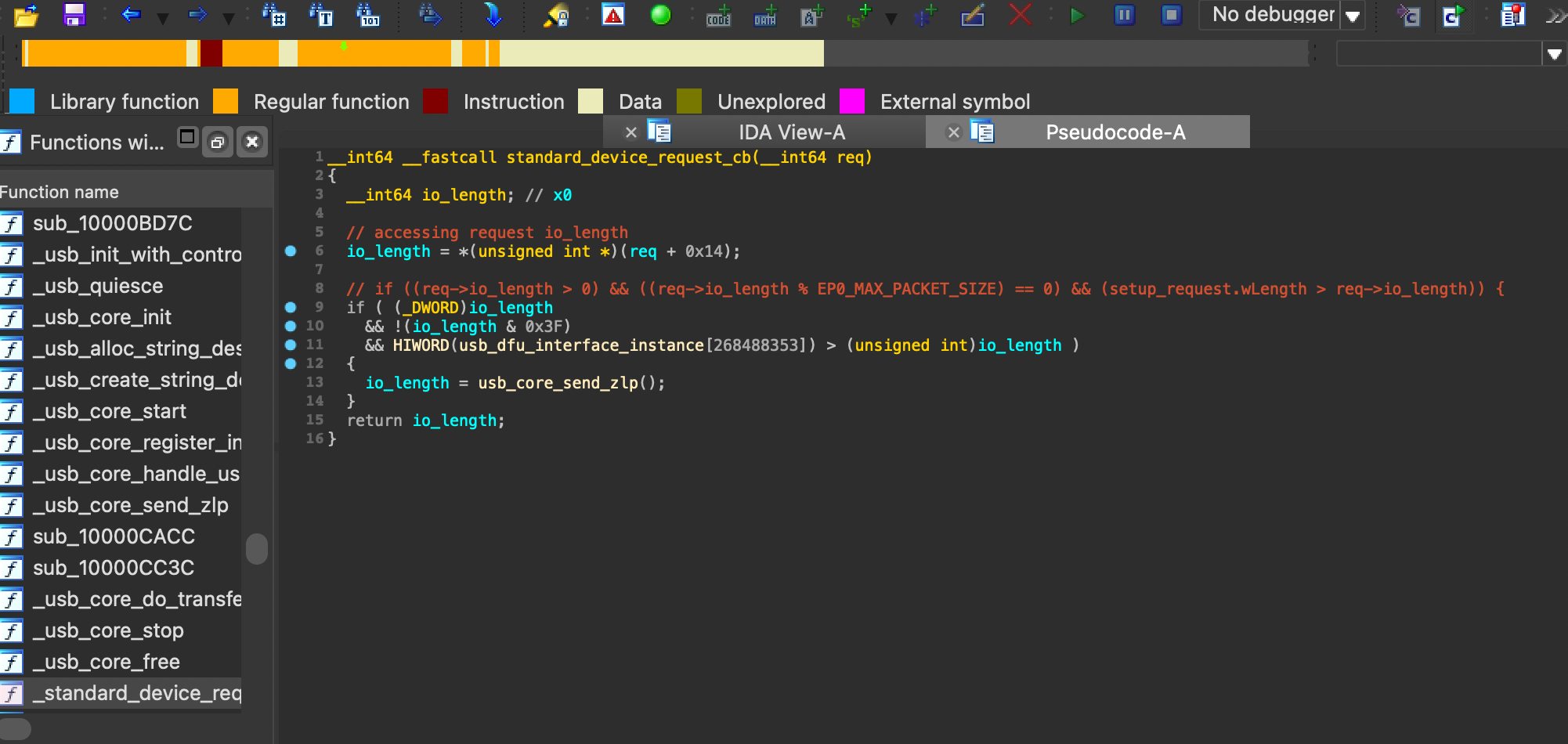
What this function is basically doing is that a ZLP packet will be added to the execution queue only if the request is a Standard Device Request, has a wLength that is more than 0x0 plus is an exact multiple of 0x40 (corresponding to the EP0_MAX_PACKET_SIZE) and finally if the host has requested more bytes than the current wLength global variable (completing the STATUS phase we have seen at the beginning… phew-).
As I previously said earlier, the usb_quiesce(...) function will shutdown the USB Stack and the endpoints will be aborted then stopped (based on the synopsys_otg_abort_endpoint() function).
In this process, it appears that the remaining pending requests will be processed as aborted, which will trigger the callback of each of them (based on the usb_core_complete_endpoint_io() function).
Based on the slides, we saw that once a request is complete for packets that are meeting the conditions we’ve seen earlier, a ZLP packet should be sent, but in this situation, it will not be sent, leading to a Memory Leak (because the ZLP packet will be queued but never sent).
If you combine up all of these informations, you can easily guess that we have a great vector of attack: stalling the IN endpoint to stack up every requests we need and then trigger a USB Reset to trigger the callback of each of them, which will queue additional ZLP packets that will be leaked.
0x33. Overview
I talked a lot from now, but we should have a pretty good vector of attack and clear view about what we have to do in order to achieve a full exploit at this point!
This is a really quick overview of the exploitation process, I didn’t detailed the
Use-After-Freepart since it was already explained earlier
In other very brief words, we will have to:
re-shape the heap in order to move the
io_bufferfurther away from the former one’s address on the nextDFUiteration using theMemory Leak, creating aholewhere the buffer should be placed in: this is theHeap Grooming,trigger the
Use-After-Freevulnerability so the global variables will not be reinitialized and, as the nextio_bufferwill be placed further away from the former one’s address, we could then write to the former address (the one of the freed buffer),finally, we will have to a payload that would first overwrite the
callbackandnextfields of theusb_device_io_requeststructure and then point to the patches, allowing us to achieve code execution.
However, there’s still a last issue: the USB limitations.
Because from what I understood, we have to “abuse” of the usual USB transfers specifications if we want to trigger the UaF with the “incomplete DATA phase” (because yes, that type of behavior would basically not be allowed in the first place), and there’d be two ways:
the one used by @littlelailo: which consists of the usage a “cheap controller” (such as an
Arduinoor aRaspberry Pifor example) that would allow us to to completely control theUSB Stackand send packets that would not be normally allowed (such as partiel control transfers so, etc.),the one used by @axi0mx: which consists of not using any external controller but instead, abusing of the
USB Stack(of the hostOS) allowing interrupted transfers (but I will talk about this later).
The most used one is the second one as not everyone can afford such controllers, so I will stick to that one too (that’s the main reason of why I did not follow @littlelailo’s exploitation advices anymore).
0x34. Heap Grooming
This is the first part of the exploitation: the one that will allow us to prepare everything in order to move the io_buffer further away from its address on the next DFU iteration using the Memory Leak (pretty much the most important one in my opinion).
In order to do so, we have to use a technique not that unknown when dealing with an Use-After-Free vulnerability are involved: the Heap Grooming.
This part will then be used for “tweaking” (either re-shape or fulfill) the heap, allowing us to control exactly the flow and be sure of the location of the data we’re about to place in.
We actually need this part here in order to access to the freed io_buffer from the previous iteration of DFU and thus, by creating a hole where the new io_buffer would be allocated in (malloc() would then allocate the io_buffer in the hole we’ve created since it would likely be more “efficient”).
The Heap is a region of memory used for dynamic memory allocation (for objects like
io_bufferfor example), you can see it as a small box: similar to how you can place/remove items in and out of a box, there, you can allocate/deallocate memory dynamically, allowing you to manage and use memory as needed during the execution.
If you need more concrete examples, you can check out this article or this video to learn more about this technique.
So, how could we then get to our desired point in there?
On the paper and based on what we’ve seen earlier, we have to:
- Stall the
INendpoint of theDEVICE2HOSTrequest, - Send multiple requests that will be queued in the linked list of requests,
- Making sure that the two extremities (first and last) of the sent requests are good enough to send a
ZLP, - Trigger an
usb_reset()so all of these requests will be leaked.
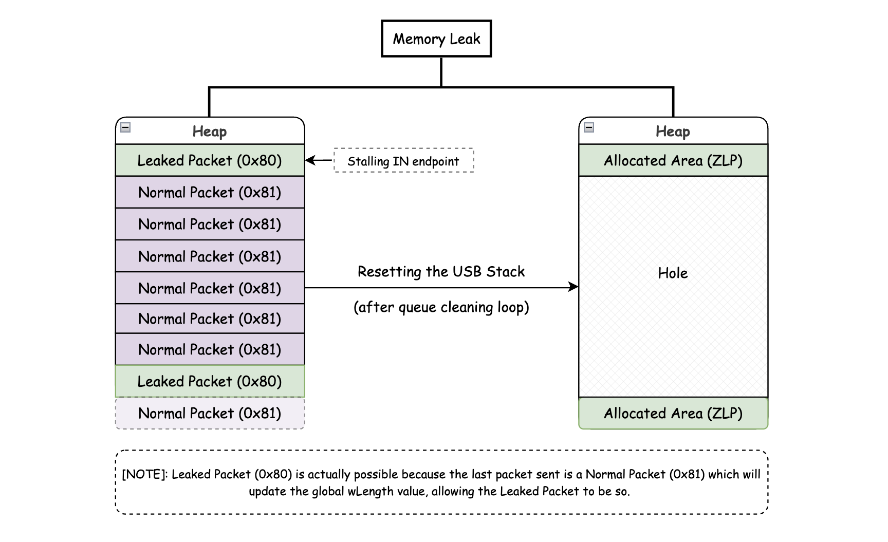
Eventually, before triggering the usb_reset(), a last request (which does not meet the requierements to send a ZLP packet) will be sent in order to update the wLength global variable.
Why? Because each times a request is sent, the wLength global variable will be updated to the length of the incoming request.
However, one of the conditions to send a ZLP packet is that the wLength global variable is bigger than the length of the request sent, which would not be the case if the last request we would send would be one that would meet the requierements to send a ZLP packet.
That’s why, in order to prevent that, we have to send a request that will not meet the requierements while having a bigger size than the last request sent to send a ZLP packet.
For example, if we would send 0x81 as a last packet, the wLength global variable would be updated to this value, so in the next DFU iteration, every leaked packet that has for value 0x80 (these values are used as example) would be sent (as 0x80 < 0x81).
So with an abridged draw, here’s how the heap would be shaped before and after:
Note that the first Leaked Packet being the Stalled
INendpoint is because it is actually possible to stall and leak at the same time, which is what we want here (c.f ipwndfu).
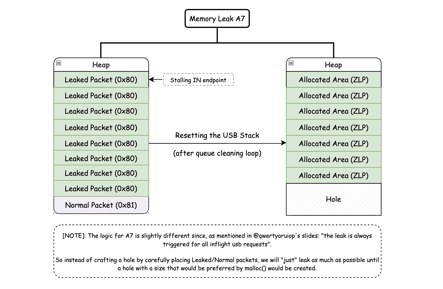
However, this is not really how it would look like for some older devices such as the A7/A6/… ones as “the leak is always triggered for all inflight usb requests” (as @qwertyoruiop said).
So instead, the Heap Grooming would become a Heap Spraying, and would look like this:
The
Heap Sprayingconsists of filling the heap with a lot of objects until a certain point, where theHeap Groomingconsists of re-shaping the heap (both aims to control the heap in order to place data where we want).
0x35. Use-After-Free (Trigger)
Once the Heap Grooming has been executed, the new io_buffer should be allocated somewhere else than its usual address, allowing us to now trigger the Use-After-Free in order to write to the freed io_buffer address from the previous iteration of DFU.
Based on the everything we’ve seen since the beginning, here’s what we would have to do:
Send a
SETUPpacket handled by theInterfacecode (because we will send aDFU_DNLOAD (0x1)request) with awLengththat is smaller than/equal to theio_bufferlength (which is0x800),Begin the
DATAphase but cancelling it mid-way (so the global variables will not be cleared),Send a
DFU_ABORT (0x6)request, freeing theio_bufferand makingDFUre-enters.
One of the points which never got any mention of in this post is the usage of an asynchronous transfer.
We indeed have to send an asynchronous (or non-blocking) transfer with a pretty short timeout, as these transfers are more likely to be interrupted (which is what we need here in order to leave the DATA phase incomplete), where synchronous (like libusb_control_transfer(...) for example) transfers are not.
It’s only when we successfully exited the DATA phase that we can send the DFU_ABORT request in order to shutdown the USB Stack and re-enter in DFU mode with the UaF triggered.
The usage of a short
timeoutis important because if the operation doesn’t complete within the defined time, the transfer becomes interrupted and moves on to the next part, leaving theDATAphase incomplete.
At this point of the exploitation, the io_buffer from the new iteration should have been allocated in the hole we’ve created thanks to the Heap Grooming, and the global variables have the values we wanted!
Starting from this moment, each time we will send data to the device, it will be written to the old io_buffer address, allowing us to write to the freed buffer, we can now insert a payload in order to try to gain code execution!!
I will dedicate a whole GitHub repo for this exploit with comments for every parts of the exploit.
0x36. Payload
This part is in fact composed of two sub-parts: the overwrite and the actual payload itself (I must confess: I peeked at ipwndfu for this part).
The
overwritepart is containing enough data to overwrite thecallbackandnextfields from ausb_device_io_requeststructure objects which will redirect the current execution flow to the payload.And the payload is an
ARM64 Assemblycode that will “simply” apply some patches (patch theUSBString of the device toPWNED:[checkm8], apply signature checks patches, etc.).
0x361. Overwrite
If you remember well, in the part that would trigger the Memory Leak, I said this:
1
2
3
In this process, it appears that the remaining pending requests will
be processed as aborted, which will trigger the callback of each of them
(based on the usb_core_complete_endpoint_io() function).
Once this function would be executed, each pending request would have their callback being called and, I did not mention it but the usb_device_io_request object (the request itself) would be freed and NULLed.
But, the fact that the object would be freed and NULLed is not a good thing because as we would have overwritten the data in the heap, freeing the request would likely leads to an invalid heap metadata, leading as well to a potential panic.
Luckily, this function “only” calls the callback then frees and NULL the object, so with some techniques, we could “skip” the freeing part.
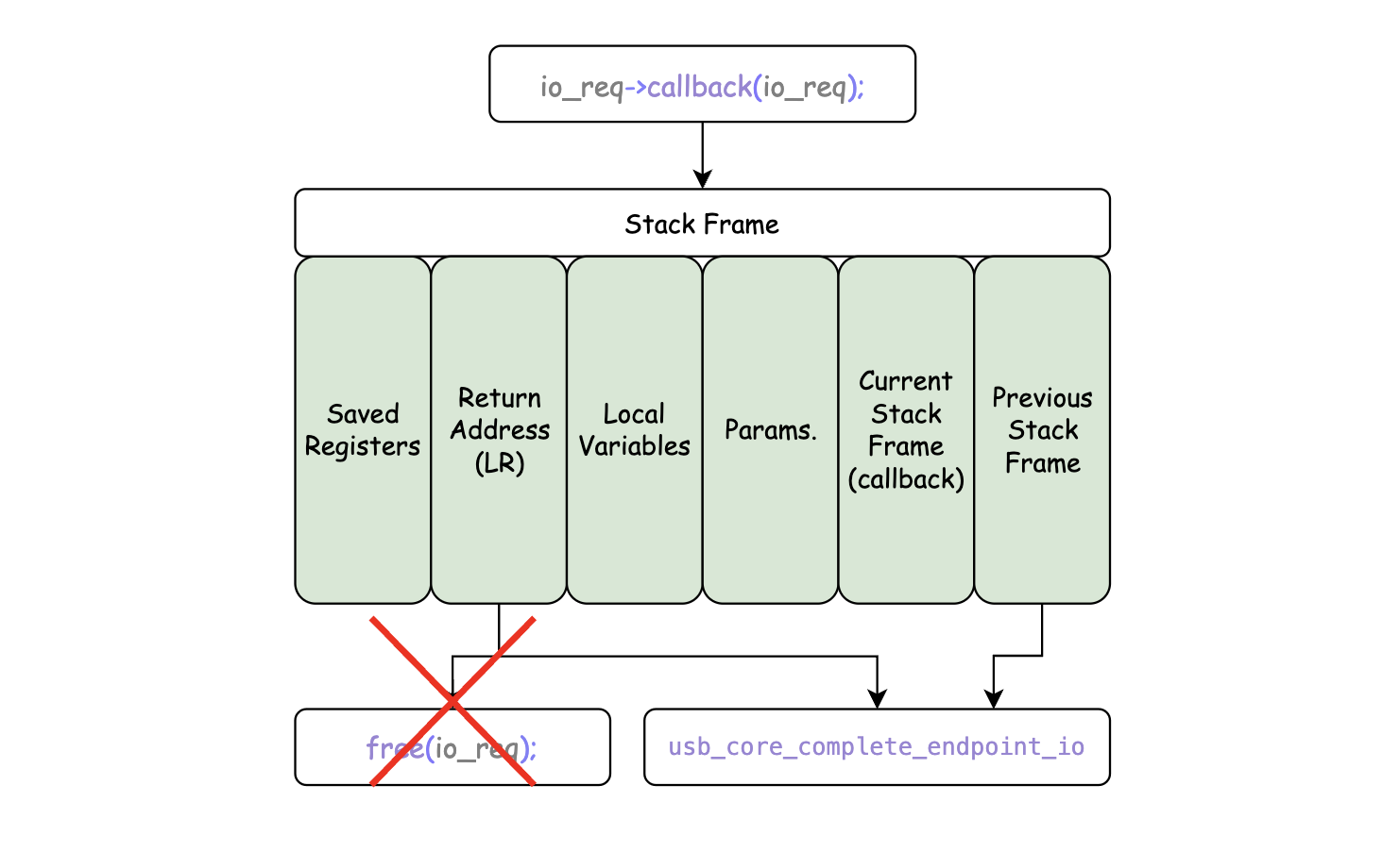
This could actually be achieved by restoring the Link Register to the address of the usb_core_complete_endpoint_io(...) function.
The Link Register (also known as LR) is a register (x30 in arm64) that is used to store the next address that should be jump back to after returning from a function (it then, changes every time a function is called).
And, restoring a register means that we will give back the address/value of a previously saved register (in this case, the address of the usb_core_complete_endpoint_io(...) function would be stored in the LR register instead of the next instruction address).
Using this technique, we could then restore the LR register to the address of the usb_core_complete_endpoint_io(...) function when the callback would be returned, allowing us to skip/avoid/prevent the request from being freed, avoiding the heap corruption and so making the device panicking.
note that we also need to restore the
FP(Frame Pointer) register in order to keep a proper validStack Frameand avoid a potentialStack Corruption.
A7/A6/… doesn’t require to restore the LR/FP registers to the usb_core_complete_endpoint_io(...) function as the exploitation method is different (as said earlier, we used a Heap Spraying), so I believe that the heap is not corrupted as the Heap Grooming would do.
Instead, the fields will be overwritten as a “typical” exploitation method (meaning that the the fields will be overwritten only with some random data in order to reach our fields + the payload address that next will point to).
For every other platforms, the previous explaination will be applied using a ROP gadget:
1
2
3
4
5
__asm__ __volatile__(
    "ldp x29, x30, [sp, #0x10]\n" // loads/restores the values of x29 and x30 from the SP
    "ldp x20, x19, [sp], #0x20\n" // loads the values of x20 and x19 from the SP (also increments the SP by `0x20` bytes for alignment)
    "ret" // jumping back to the address stored in LR (now `usb_core_complete_endpoint_io(...)` function)
);
Technically, this gadget in itself doesn’t do any major operations, but does enough to achieve the goal of skipping the freeing part of the request!
Inside the overwrite should be included the payload address (also called LOAD_ADDRESS in some projects configuration).
This address is corresponding to the INSECURE_MEMORY_BASE, which is, as I said earlier, the memory location from where the firmware (IMG4 etc.) is later booted, but instead of placing an image, the payload will be placed there.
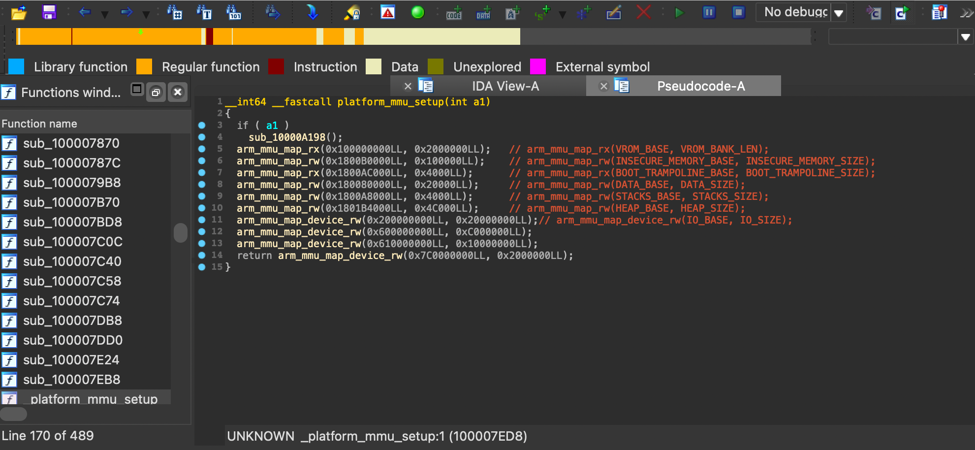
The address of the INSECURE_MEMORY_BASE for each platform can either be found in the iBoot source code (in memmap.h include files) or by reversing the SecureROM and searching for the platform_mmu_setup(...) function.
Be aware that not every platform are setting up the
INSECURE_MEMORY_BASEaddress in this function (this screen shows it for thet8010(A10) but for example,s5l8960(A7) does not have it).
At this point, the overwrite part should be done so the payload should be sent and an USB reset should be trigger as well, processing every cancelled requests remaining in the queue and calling their callback as well (which is what we just seen).
0x362. Payload
Our payload should now be loaded at the INSECURE_MEMORY_BASE address, however for some devices, the execution flow is pointing up on a “callback-chain”, but what is it exactly?
From what I understood, this chain is somehow playing a major role as it sets up a required environment for the exploit to succeed by disabling security features, managing the processor state, memory mappings, and more.
Here’s an example of a callback-chain for the t8010 (A10) platform from ipwndfu:
1
2
3
4
5
6
7
8
9
10
11
12
t8010_callbacks = [
    (t8010_dc_civac, 0x1800B0600), # clearing the virtual cache
    (t8010_dmb, 0), # data memory barrier used to ensure that all memory accesses are completed before the next instruction is executed
    (t8010_enter_critical_section, 0),
    (t8010_write_ttbr0, 0x1800B0000), # 0x1800B0000 being the INSECURE_MEMORY_BASE, this will redirect the translation table base register to the shellcode
    (t8010_tlbi, 0), # invalidating the TLB (which is cache storing recent translations of virtual memory to physical memory), ensuring that the new translation table base register is used
    (0x1820B0610, 0), # appears to be the WXN disable function
    (t8010_write_ttbr0, 0x1800A0000), # restoring the translation table base register as the data in the INSECURE_MEMORY_BASE will be overwritten
    (t8010_tlbi, 0), # invalidating the TLB again
    (t8010_exit_critical_section, 0),
    (0x1800B0000, 0), # redirect to shellcode
]
Here, the biggest purpose was to disable WXN (Write XOR Execute Never, which prevents the execution of code from a writable memory region) and redirect the execution flow to the shellcode, so the shellcode could be executed without any issues.
The callback-chain is not for every devices, it’s only required for
A10and above devices, others will directly jump to the payload address.
Finally, the shellcode from ipwndfu is an ARM64 Assembly code that will apply some patches to the device.
I won’t detail every lines but rather explain some parts of it in the order:
- Restoring the USB Descriptors as we damaged them in the heap grooming part,
- Overwriting the USB Serial Number by
PWNED:[checkm8], - Overwriting the USB request handler used for the next point,
- Handling USB requests and executing custom commands when the device will receive a new request, the new handler (of the 3rd point) will check if the request’s
wValueis equal to0xffff, allowing to execute commands such as memcpy, memset, and exec. In the opposite case, the request will be handled by the default handler.
The shellcode is the part that will apply the patches to the device, you can also add your own patches to it if you want to, keep in mind that ipwndfu’s shellcode is a just the bare minimum.
Afterwards, your device should be placed in pwnedDFU mode and you should be able to play with it as much as you want, closing also this whole article. I hope you’ve learned something from it and that you enjoyed reading it!!
A project summarizing all of this will be made, so this post will be updated as well with a link to it (probably targetting A7 devices as this is the only device I own) :)
0x4. Conclusion
This exploit is really complex (I for sure did not cover every details but most the explaination is here at least) and I realized by the end of this article that I might have picked a really strong subject for my first exploitation post (clown_face.png).
The Use-After-Free vulnerability is a pretty common one, but the exploitation was kind of hard to understand (and to write), but so was the Memory Leak (which was probably the most complex one here-) because the whole logic is really complex and above all, I did a mistake by thinking I could understand the exploit without having the basics of exploitation: I was STUPID and WRONG.
That’s why, in order to understand what’s going on (why such thing is doing that and what is that thing and […]), I had to learn somehow pretty quickly the fundamentals of the art of exploitation (what is/how to use ROP attacks and why, how is a stack/heap truly working, how to achieve Stack/Buffer/Heap Overflows, how to rightfully use GDB/LLDB and know the purpose of registers in runtime, how does malloc()/free() are deeply working, …).
I certainly did not cover every details of the exploit (in particular the most technical ones), but I tried to make it as understandable as possible (and I hope I did it well-).
Anyways, this exploit was a really good example of “real-life vulnerabilties”: it asked for carefulness, patience, a stack of exploitation techniques + a stack of development and a lot of researches… but in the end, if you managed to follow until there, you should have ganined few more knowledges!!
Once again, if I ever said something wrong, please correct me!!
You can follow me on my twitter if you liked this post and you can also support me by looking at my projects on GitHub!
Thank you for your time. ヾ(・ω・*)

